- 您现在的位置:买卖IC网 > Sheet目录366 > TMDXEVM5515 (Texas Instruments)EVAL MODULE DSP FOR C55XX
�� ���
���
���SPRS645F� –� AUGUST� 2010� –� REVISED� OCTOBER� 2013�
�5� Peripheral� Information� and� Electrical� Specifications�
��5.1�
�Parameter� Information�
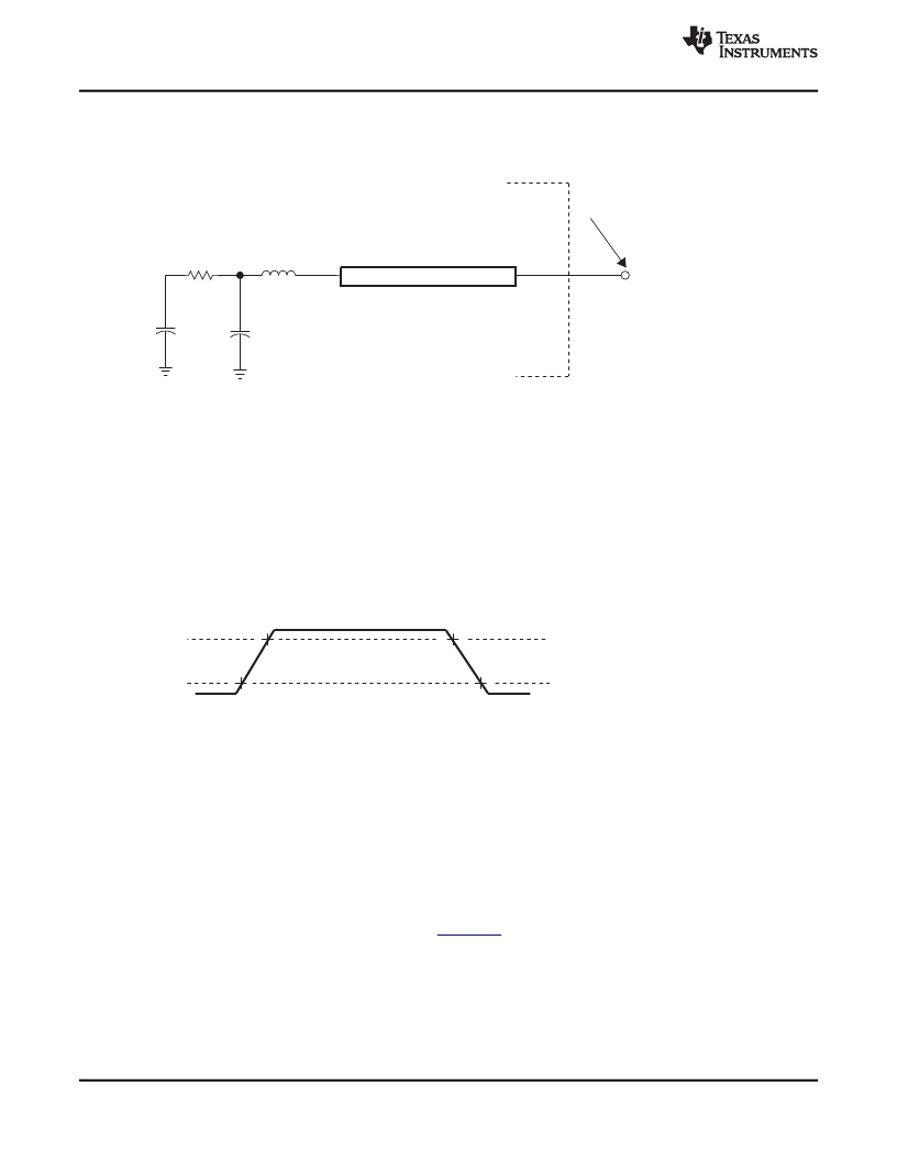
�Tester� Pin� Electronics�
�Data� Sheet� Timing� Reference� Point�
�42�
�4.0� pF�
�3.5� nH�
�1.85� pF�
�Transmission� Line�
�Z0� =� 50�
�(see� Note)�
�Output�
�Under�
�Test�
�Device� Pin�
�(see� Note)�
�NOTE:� The� data� sheet� provides� timing� at� the� device� pin.� For� output� timing� analysis,� the� tester� pin� electronics� and� its� transmission� line� effects� must� be�
�taken� into� account.� A� transmission� line� with� a� delay� of� 2� ns� can� be� used� to� produce� the� desired� transmission� line� effect.� The� transmission� line� is�
�intended� as� a� load� only.� It� is� not� necessary� to� add� or� subtract� the� transmission� line� delay� (2� ns)� from� the� data� sheet� timings.�
�Input� requirements� in� this� data� sheet� are� tested� with� an� input� slew� rate� of� <� 4� Volts� per� nanosecond� (4� V/ns)� at� the� device� pin.�
�Figure� 5-1.� 3.3-V� Test� Load� Circuit� for� AC� Timing� Measurements�
�The� load� capacitance� value� stated� is� only� for� characterization� and� measurement� of� AC� timing� signals.� This�
�load� capacitance� value� does� not� indicate� the� maximum� load� the� device� is� capable� of� driving.�
�5.1.1�
�5.1.2�
�5.1.3�
�5.2�
�1.8-V,� 2.5-V,� 2.75-V,� and� 3.3-V� Signal� Transition� Levels�
�All� rise� and� fall� transition� timing� parameters� are� referenced� to� V� IL� MAX� and� V� IH� MIN� for� input� clocks,� V� OL�
�MAX� and� V� OH� MIN� for� output� clocks.�
�V� ref� =� V� IH� MIN� (or� V� OH� MIN)�
�V� ref� =� V� IL� MAX� (or� V� OL� MAX)�
�Figure� 5-2.� Rise� and� Fall� Transition� Time� Voltage� Reference� Levels�
�3.3-V� Signal� Transition� Rates�
�All� timings� are� tested� with� an� input� edge� rate� of� 4� volts� per� nanosecond� (4� V/ns).�
�Timing� Parameters� and� Board� Routing� Analysis�
�The� timing� parameter� values� specified� in� this� data� manual� do� not� include� delays� by� board� routing.� As� a�
�good� board� design� practice,� such� delays� must� always� be� taken� into� account.� Timing� values� may� be�
�adjusted� by� increasing/decreasing� such� delays.� TI� recommends� utilizing� the� available� I/O� buffer�
�information� specification� (IBIS)� models� to� analyze� the� timing� characteristics� correctly.� To� properly� use� IBIS�
�models� to� attain� accurate� timing� analysis� for� a� given� system,� see� the� Using� IBIS� Models� for� Timing�
�Analysis� application� report� (literature� number� SPRA839� ).� If� needed,� external� logic� hardware� such� as�
�buffers� may� be� used� to� compensate� any� timing� differences.�
�Recommended� Clock� and� Control� Signal� Transition� Behavior�
�All� clocks� and� control� signals� must� transition� between� V� IH� and� V� IL� (or� between� V� IL� and� V� IH� )� in� a� monotonic�
�manner.�
�72�
�Peripheral� Information� and� Electrical� Specifications�
��Product� Folder� Links:� TMS320C5515�
�Copyright� ?� 2010–2013,� Texas� Instruments� Incorporated�
�发布紧急采购,3分钟左右您将得到回复。
相关PDF资料
TMDXEXP1808L
KIT EXPERIMENTER FOR AM180X
TO263-3EV-VREG
BOARD EVAL TO220-3/TO263-3 VREG
TO263-5EV-VREG
EVAL BOARD VREG TO220-5/TO263-5
TOOLSTICK-EK
KIT TOOL EVAL SYS IN A USB STICK
TPS23757EVM
EVALUATION MODULE FOR TPS23757
TPS62230EVM-370
EVAL MODULE FOR TPS62230-370
TRAVELCUBE
SURGE SUP 1OUT W/RJ11 DIRECTPLUG
TRAVELER100BT
SURGE SUP 2OUT W/RJ11 DIRECTPLUG
相关代理商/技术参数
TMDXEVM5515
制造商:Texas Instruments 功能描述:TMS320C5515 DSP Evaluation Module
TMDXEVM642
制造商:Texas Instruments 功能描述:Tools Development kit For Use
TMDXEVM6424
功能描述:开发板和工具包 - TMS320 C6424 DSP Eval Mod RoHS:否 制造商:Texas Instruments 产品:Experimenter Kits 工具用于评估:F2802x 核心:TMS320 接口类型:UART, USB 工作电源电压:
TMDXEVM6446
制造商:Rochester Electronics LLC 功能描述:DAVINCI EVM BUNDLE W/O EMULATOR - Bulk 制造商:Texas Instruments 功能描述:DAVINCI EVM BUNDLE W/O EMULATOR - Bulk
TMDXEVM6446T
制造商:Texas Instruments 功能描述:DM6446 DIGITAL VIDEO EVALUATION MODULE - Boxed Product (Development Kits)
TMDXEVM6446TS
制造商:Texas Instruments 功能描述:DM6446 DIGITAL VIDEO EVALUATION MODULE - Trays
TMDXEVM6452
功能描述:开发板和工具包 - TMS320 C6452 EVM Evaluation Module RoHS:否 制造商:Texas Instruments 产品:Experimenter Kits 工具用于评估:F2802x 核心:TMS320 接口类型:UART, USB 工作电源电压:
TMDXEVM6455
功能描述:开发板和工具包 - TMS320 C6455 Evaluation Module RoHS:否 制造商:Texas Instruments 产品:Experimenter Kits 工具用于评估:F2802x 核心:TMS320 接口类型:UART, USB 工作电源电压: